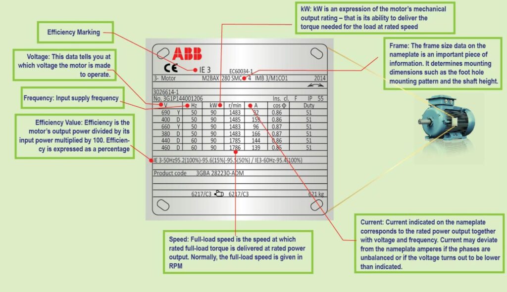
We have all seen the motor nameplate attached on the motor side (or on top). All motors have a permanent nameplate which lists all important data; further data is usually available in the motor catalogue.
The name plate of the motor provides important information necessary for proper identification, ordering, replacement and application.
However, when a motor has been in operation for a long time, it is often not possible to determine its operating information because nameplates of motors are often lost or painted over. Its always recommended to record motor data’s and name plate picture for future use.
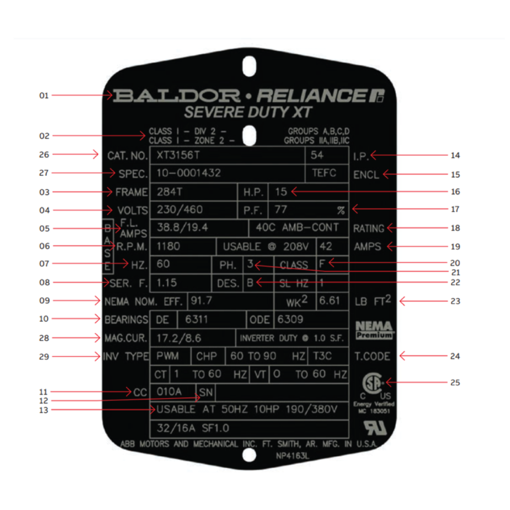
How to read a NEMAmotor nameplate
Glossary of frequently occurring motor terms
Frame size (FRAME):
Motor dimension standardization is indicated by the frame size. This number reflects the same mounting and shaft information between different manufacturers in order to be consistent.
NEMA frame size refers to mounting interfaces only, it has no direct bearing on the motor body diameter.
IEC Frame indicates the shaft height of the motor.
Rated voltage (VOLTS):
This data indicates the voltage at which the motor is designed to operate most efficiently; however, a motor can still operate effectively at plus or minus a 10 percent tolerance of this value. For example, a motor with a 460V rating could operate effectively at around 414V to 506V. The nameplate-defined parameters for the motor – such as power factor, efficiency, torque and current – are at rated voltage and frequency. When the motor is used at other voltages than the voltage indicated on the nameplate, its performance will be affected.
Rated full load speed (R.P.M.):
The rated full load speed is the speed at which full load torque is delivered for the rated voltage and frequency. The difference between the full load speed and the synchronous speed is called slip. The motor’s slip is determined by its design. For most induction motors, generally, the full load speed can be between 96 percent and 99 percent of the synchronous speed.
Rated full-load amps (F.L. AMPS):
Full-load amps represents the amount of current the motor is designed to draw at the rated load and rated voltage. Motors with a lower F.L.A. with the same amount of horsepower are considered more efficient to operate.
Frequency (HZ):
Hertz is measured in cycles per second. This is the frequency of input power for which the motor is designed to operate at the rated output power, voltage and speed. To operate successfully, the motor frequency must match the power system (supply) frequency. If more than one frequency is marked on the nameplate, then other parameters that will differ at different input frequencies have to be indicated on the nameplate as well. The most commonly occurring frequency in the United States is 60 Hertz, and the most common frequency for motors used outside the United States is 50 Hertz.
Service factor (SER. F. or S.F.):
The service factor shown on the motor nameplate indicates the amount of continuous overload the motor can be expected to handle, under nameplate conditions, without overheating or damaging the motor. When the voltage and frequency are at the same value as shown on the motor nameplate, the motor may be overloaded up to the horsepower indicated by multiplying the rated horsepower by the service factor. For example, a motor with a 1.0 service factor cannot be expected to handle more than its nameplate horsepower on a continuous basis. A motor with a 1.15 service factor can be expected to safely handle infrequent loads up to 15 percent past its rated horsepower, i.e. a 10 Hp motor could run at 11.5 Hp. The downside is this could create a hotter motor with a shortened expected life. NEMA MG1 9.15.1 States: “An induction motor operated at any service factor greater than 1.0 will have a reduced life expectancy compared to operating at its rated nameplate horsepower.”
When operated at service factor load, the motor may have an efficiency, power factor and speed slightly different from those shown on the nameplate. Service factor can also be used to determine if a motor can be operated continuously at altitudes higher than 3,300 feet satisfactorily. At altitudes greater than 3,300 feet, the lower density of air reduces the motor’s cooling ability thereby causing the temperature of the motor to be higher. This higher temperature is compensated for by reducing the effective service factor to 1.0 on motors nameplated with a 1.15 service factor or greater. If the motor is operated outdoors at higher altitudes. it’s sometimes possible to use full horsepower and full service factor since ambient temperatures are usually lower at those altitudes.
Efficiency:
Efficiency is the percentage of the input power that is converted to work output from the motor shaft. In its simplest form, efficiency is calculated by dividing the motor’s output power by its input power multiplied by 100. In actual practice, in three-phase induction motors for example, the industry standards prescribe procedures to determine the various types of losses in the motor and then sum them to determine the net losses. (The difference is very small, but the purpose of the procedure is to ensure that every manufacturer determines and reports the efficiency in a consistent manner.) The higher the percentage, the more efficiently the motor converts incoming electrical power to mechanical horsepower. Efficiency is guaranteed by the manufacturer to be within a certain tolerance band, which varies depending on the design standard, i.e. IEC or NEMA. Unused energy is converted to heat in the motor. The user pays for the energy that goes into the motor but only gets benefit from the output of the motor. The difference – the losses – are consumed and paid for with no benefit received. Energy efficiency is always important since the losses are paid for whenever the motor is running. Energy efficiency is particularly important if power costs are high or if the motor operates for long periods of time.
Bearings (DE and ODE):
Information is usually given for both the drive-end (DE) bearing and the bearing opposite the drive end (ODE). The difference between these two is the location in the motor. The drive end bearing is located close to where the drive shaft extends out of the motor. The opposite drive shaft bearing is on the opposite side of the drive shaft. The numbers indicate the bearing type and size.
Enclosure type (ENCL):
The enclosure, or housing/cooling method, for which the motor is designed. The enclosure must protect the windings, bearings and other mechanical parts from moisture, chemicals, mechanical damage and abrasion from grit.
Rated horsepower (H.P.):
Horsepower is an expression of the motor’s mechanical output rating, or its ability to deliver the torque needed for the load at rated speed. This value is based on the motor’s full-load torque and fullload speed ratings and is calculated as follows:
For an electric motor, one horsepower is equivalent to 746 watts of electrical power.
Power factor (P.F.):
Power factor is the measure of a particular motor’s requirements for magnetizing amperage. The formula “watts = amps x volts” must be altered when inductance is introduced to the load to include a new term called power factor. Thus, the new formula for single phase loads becomes “watts = equal amps x volts x power factor”. Power factor is an expression of the ratio of active power (W) to apparent power (VA) expressed as a percentage.
Ambient temperature and time rating (RATING):
The motor’s rating is the ambient (room) temperature surrounding the motor and the time it can operate at that temperature. The maximum ambient temperature at which a motor can operate is sometimes indicated on the nameplate.
Insulation class (CLASS):
Insulation classes are expressions of the thermal tolerance of the motor winding, or the winding’s ability to survive a given operating temperature for a given life. The classes are designated in order of thermal capabilities by the letters A, B, F and H. The higher the designated code letter, the greater the heat capability. For example, based on a 40°C ambient temperature, class B insulation is suitable for 80°C rise by resistance, class F suitable for 105°C rise by resistance, and class H is suitable for 125°C rise by resistance. Use of class F or class H insulation can increase the service factor or the ability to withstand high ambient temperature conditions. Class A and B systems are now rarely, if ever, used in industrial motors. It should be noted that a higher insulation class does not necessarily mean that the motor operates at that higher temperature. It is common for industrial motors to have Class F systems but operate at or near Class B rise at rated load at 1.0 service factor
Phase (PH.):
Phase is the indication of the type of power supply for which the motor is designed. The two main categories are single phase and three phase. Single phase means that only one voltage waveform is applied to the motor, while three-phase motors have three wires delivering voltage waveforms, each supplying peak voltage and current at different times. A three-phase motor is more efficient and economical, and most large industrial motors and applications rely on three-phase power
Rotor inertia:
Rotor inertia data is typically included for variable speed applications. Inertia is an object’s resistance to a change in speed. In an electromechanical system, both the motor’s rotor and load have inertia, and how similar (or different) their inertias are will affect the performance of the system. The ratio of the load inertia to the rotor inertia is an important aspect of motor sizing.
Locked rotor
The condition existing when the circuits of a motor are energized but the rotor is not turning.
Also known as starting inrush, this is the amount of current the motor can be expected to draw under starting conditions when full voltage is applied.
High inertia load:
These are loads that have a relatively high flywheel effect. Large fans, blowers, punch presses, centrifuges, commercial washing machines, and other types of similar loads can be classified as high inertia loads.
Constant Power/horsepower:
The term constant horsepower is used in certain types of loads where the torque requirement is reduced as the speed is increased and vice-versa. The constant horsepower load is usually associated with metal removal applications such as drill presses, lathes, milling machines, and other similar types of applications.
Constant torque:
Constant torque is a term used to define a load characteristic where the amount of torque required to drive the machine is constant regardless of the speed at which it is driven. For example, the torque requirement of most conveyors is constant.
Variable torque:
Variable torque is found in loads having characteristics requiring low torque at low speeds and increasing values of torque as the speed is increased. Typical examples of variable torque loads are centrifugal fans and centrifugal pumps.
Poles:
This is the number of magnetic poles that appear within the motor when power is applied. Poles always come in sets of two (a north and a south). Thus, the number of poles within a motor is always an even number such as 2, 4, 6, 8, 10, etc. In an AC motor, the number of poles work in conjunction with the frequency to determine the synchronous speed of the motor.
Slip:
Slip is used in two forms. One is the slip RPM which is the difference between the synchronous speed and the full load speed. When this slip RPM is expressed as a percentage of the synchronous speed, then it is called percent slip or just “slip”. Most standard motors run with a full load slip of 2% to 5%.
Synchronous speed:
This is the speed at which the magnetic field within the motor is rotating. It is also approximately the speed that the motor will run under no load conditions. For example, a 4-pole motor running on 60 cycles would have a magnetic field speed of 1800 RPM. The no load speed of that motor shaft would be very close to 1800, probably 1798 or 1799 RPM. The full load speed of the same motor might be 1745 RPM. The difference between the synchronous speed and the full load speed is called the slip RPM of the motor.
Temperature rise:
Temperature rise is the amount of temperature change that can be expected within the winding of the motor from non-operating (cool condition) to its temperature at full load continuous operating condition. Temperature rise is normally expressed in degrees centigrade.
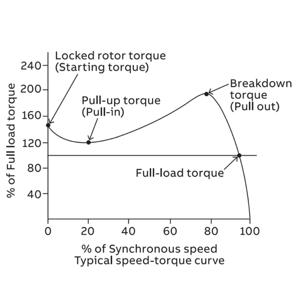
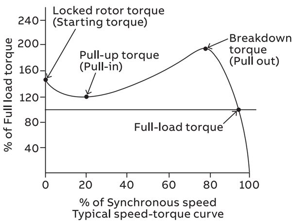
Torque:
Torque is the twisting force exerted by the shaft of a motor. Torque is measured in pound inches / Nm
Full load torque:
Full load torque is the rated continuous torque that the motor can support without overheating within its time rating.
Peak torque:
Many types of loads such as reciprocating compressors have cycling torques where the amount of torque required varies depending on the position of the machine. The actual maximum torque requirement at any point is called the peak torque requirement. Peak torques are involved in things such as punch presses and other types of loads where an oscillating torque requirement occurs.
Pull out torque:
Also known as breakdown torque, this is the maximum amount of torque that is available from the motor shaft when the motor is operating at full voltage and is running at full speed. The load is then increased until the maximum point is reached.
Pull up torque:
The lowest point on the torque speed curve for a motor that is accelerating a load up to full speed is called pull up torque. Some motor designs do not have a value of pull up torque because the lowest point may occur at the locked rotor point. In this case, pull up torque is the same as locked rotor torque.
Starting torque:
The amount of torque the motor produces when it is energized at full voltage and with the shaft locked in place is called starting torque. This value is also frequently expressed as “locked rotor torque”. It is the amount of torque available when power is applied to break the load away and start accelerating it up to speed.
Locked rotor time
Maximum time for motor circuits to be energized but the rotor is not turning
Stalled rotor
The condition existing when the rotor of a synchronous motor is turning with slip frequency and unable to accelerate up to synchronous operation
Airgap
The space between the rotating (rotor) and stationary (stator) member in an electric motor.
Altitude
The atmospheric altitude (height above sea evel) at which the motor will be operating; NEMA standards call for an altitude not exceeding 3,300 ft. (1,000 meters). As the altitude increases above 3,300 ft. and the air density decreases, the air’s ability to cool the motor decreases – for higher altitudes higher grades of insulation or a motor derating are required. DC motors require special brushes for high altitudes.
Anti-Friction Bearing
An anti-friction bearing is a bearing utilizing rolling elements between the stationary and rotating assemblies
Brush
A piece of current conducting material (usually carbon or graphite) which rides directly on the commutator of a commutated motor and conducts current from the power supply to the armature windings.
Duty Cycle
The relationship between the operating and rest times or repeatable operation at different loads. A motor which can continue to operate within the temperature limits of its insulation system, after it has reached normal operating (equilibrium) temperature is considered to have a continuous duty (CONT.) rating. One which never reaches equilibrium temperature, but is permitted to cool down between operations is operating under intermittent duty (INT.) conditions such as a crane and hoist motor which are often rated 15 or 30 min. duty
Eddy Currents
Localized currents induced in an iron core by alternating magnetic flux. These currents translate into losses (heat) and their minimization is an important factor in lamination design.
Hysteresis
A lagging of the resulting magnetization in a ferromagnetic material caused by a changing magnetic field.
Hysterisis Loss
The resistance to becoming magnetized (magnetic orientation of molecular structure) offered by materials results in energy being expended and corresponding loss. Hysterisis loss in a magnetic circuit is the energy expended to magnetize and demagnetize the core.
Impedance
Propensity of a circuit or device to impede the flow of current. The real part of impedance is the resistance, and the imaginary part is the reactance
Inductance
Represents the propensity of a conductor to store energy in an associated magnetic field. Opposes the change of alternating current, but does not oppose the flow of steady current, such as direct current. Can be thought of as electrical inertia
InductionMotor
An induction motor is an alternating current motor in which the primary winding on one member (usually the stator) is connected to the power source and a secondary winding or a squirrel-cage secondary winding on the other member (usually the rotor) carries the induced current. There is no physical electrical connection to the secondary winding, its current is induced.
Inverter
An electronic device that converts fixed frequency and voltage to variable frequency and voltage.
Inverter
An electronic device that converts fixed frequency and voltage to variable frequency and voltage.
Magnetic Field
The portion of space near a current-carrying body or a magnetic body in which a voltage can be induced in a second current carrying body when the state of changes or when the second current-carrying body moves in prescribed ways relative to the medium.
Magnetic Flux
The integral over a specified surface of the component of magnetic induction perpendicular to the surface.
Alignment
A condition where the components of a machine are coincident, parallel, or perpendicular, according to design requirements. Misalignment is the condition where the desired coincidence, parallelism, or perpendicularity is not achieved, and it causes abnormally high wear and power consumption in the machine. The procedure to correct misalignment is also called “alignment”
Amplitude
The magnitude, or amount, of displacement, velocity, or acceleration, measured from the “at rest” value. The amplitude of a vibration signal can be expressed in terms of “peak” level, “Peak-to-peak” level, or RMS level. It is somewhat of a de facto standard that Displacement is peak-to-peak, Velocity is peak, and Acceleration is RMS.
Balancing
The adjustment of the mass distribution of a rotating member so that the forces on the bearings due to centrifugal effects are reduced to small values. The rotor is balanced if the center of the mass distribution is coincident with the center of rotation. Balancing reduces power consumption in machines, reduces vibration levels, and increases bearing life, sometimes greatly.
Cavitation
Cavitation is a condition that often occurs in pumps and water turbines where reduced fluid pressure results in bubbles forming near the surface of the rotor. When these bubbles collapse, relatively large forces are transmitted to the rotor, and eventually it will cause pitting of the surface. Cavitation in pumps commonly happens when the inlet pressure is too low. It causes high-frequency random noise in the spectrum of the machine.
Center of Gravity
In a mechanical structure, the center of gravity is the point within the structure where the mass seems to be concentrated. If suspended from the center of gravity, the structure would be in equilibrium, and would not tend to rotate due to gravitational attraction. If thecenter of gravity of a rotor lies on its axis of rotation, the rotor is said to be statically balanced.
Critical Speed
The critical speed of a rotor is an operating range where turning speed equals one of its natural frequencies due to bending or torsional resonances. If a rotor is operated at or near a critical speed, it will exhibit high vibration levels, and is likely to be damaged. Much rotating equipment is operated above its lowest critical speed, and this means it should be accelerated relatively rapidly so as not to spend any appreciable time at a critical speed.
Eccentricity
Eccentricity is the deviation from circularity of a part, such as a rotor or a shaft. In electric motors, eccentricity of the rotor causes undue vibration of the motor due to non-symmetrical magnetic effects. Eccentricity of the stator also causes magnetic effects which increase the vibration level.
Eddy Current
Eddy currents are electric currents induced in electrically conducting materials by fluctuating magnetic fields. They cause heating of the metal, and are thus wasters of power. A practical use for eddy currents is the eddy current probe, or proximity probe.
Foundation
The supporting structure for a machine is generally called the foundation, and it is vitally important to the proper operation of the machine. Loose, flexible, or cracked foundations are the cause of many machine problems, especially misalignment.
Harmonics
Harmonics, also called a harmonic series, are components of a spectrum which are integral multiples of fundamental frequency. A harmonic series in a spectrum is the result of a periodic signal in the wave form. Harmonic series are very common in spectra of machinery vibration.
Imbalance
A condition of a rotating part where the center of mass does not lie on the center of rotation. Imbalance of a rotor causes a centripetal force at the frequency of the rotation rate to be applied to the bearings. If it is large, it can severely shorten the life of the bearings, besides causing undue vibration of the machine. Forces caused by imbalance are proportional to the square of the RPM, and this means that high-speed machines must be balanced to a higher standard than low-speed machines.
Natural Frequency
The natural frequency is the frequency at which a mechanical system will continue to vibrate after the excitation signal is removed. It is sometimes called the resonant frequency, but this is inaccurate, for the resonant frequency is the frequency at which it would vibrate if there were no damping. See also Free Vibration.
Lorem ipsum dolor sit amet, consectetur adipiscing elit. Ut elit tellus, luctus nec ullamcorper mattis, pulvinar dapibus leo.
BRAKES
An external device or accessory that brings a running motor to a standstill and/or holds a load. Can be added to a motor or incorporated as part of it
LOSSES
A motor converts electrical energy into a mechanical energy and in so doing, encounters losses. These losses are all the energy that is put into a motor and not transformed to usable power but are converted into heat causing the temperature of the windings and other motor parts to rise.
RTD (Resistance Thermal Detectors)
Winding RTD A resistance device used to measure temperature change in the motor windings to detect a possible over heating condition. These detectors are embedded into the winding slot and their resistance varies with temperature.
Bearing RTD/BTD:A probe used to measure bearing temperature to detect an overheating condition. The RTD’s resistance varies with the temperature of the bearings.
RESISTANCE
The degree of obstacle presented by a material to the flow of electric current is known as resistance and is measure to Ohms
ROTATING MAGNETIC FIELD
The force created by the stator once power is applied to it that causes the rotor to turn
Get A Quote
Please fill out the form below and we will get back to you as soon as possible with a quote.
In case of urgency please call us at +971-6-7666300. Thank you.